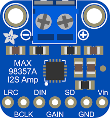
When I started my AI Powered Skelly project built with a Radxa Zero 3 I quickly discover that the board does not ship with on‑board audio. This was a problem, because I really wanted to utilize the existing speaker within the 3ft Dancing Skeleton animatronic as a more natural source of audio output. To solve this I choose to use a MAX98357A mono amplifier to drive audio output to small speaker. This article walks you through everything you need to get the MAX98357A working on a Radxa Zero 3, from wiring the pins to enabling I2S software and finally creating the custom device‑tree overlay that makes the kernel aware of the hardware.
Why Choose MAX98357A for Radxa Zero 3?
| Feature | MAX98357A | Typical Alternatives |
|---|---|---|
| Power consumption | < 100 mW (idle) | > 200 mW for many DACs |
| Output type | Mono, 3 W Class‑D | Stereo, often larger footprint |
| Interface | I2S digital audio input only | PCM/I2C/USB combos |
| Gain control | Fixed (9 dB default) or external pin | Variable via software registers |
| Shutdown pin | Optional hardware line | Often not present |
Because the amplifier needs only three I2S signals (BCLK, LRCK and DATA) plus power and ground, it can be wired directly to the standard I2S pins on the Radxa Zero 3 without any extra level shifters. The board’s 5 V rail supplies the amplifier’s VIN, while the GND pins provide a clean reference.
GPIO Pinout – Mapping MAX98357A to Radxa Zero 3
The Radxa Zero 3 exposes its I2S‑3 controller (named I2S3_M0) on the following header pins:
| MAX98357A pin | Function | Radxa Zero 3 Pin # | SoC GPIO name |
|---|---|---|---|
| VIN | 5 V power | 2 or 4 5v | VDD_5V |
| GND | Ground | 6, 9, 14, 20, 25, 30, 34, 39 | GND |
| BCLK | I2S Bit Clock | 12 | I2S3_SCLK_M0 |
| DIN (DATA) | I2S Serial Data In | 40 | I2S3_SDO_M0 |
| LRC (LRCK) | I2S Left‑Right Clock | 35 | I2S3_LRCK_M0 |
| GAIN (optional) | Fixed gain selector – connect to GND for 6 dB, leave floating for default 9 dB | any free GND (e.g., 20) | GND |
| SD (Shutdown) | Active‑low shutdown – pull low to mute | any free GPIO (e.g., 16 with optional PWM) | GPIO3_B1/PWM8_M0 |
Tip: The GAIN and SD pins are optional. For a simple “always on” configuration you can leave them floating. If you need hardware mute, connect the SD pin to a spare GPIO and drive it low when you want silence.
Wiring Diagram
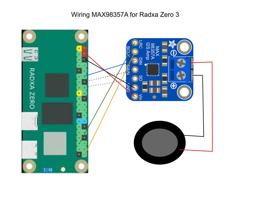
Radxa Zero 3                 MAX98357A
---------------------------  -----------------
Pin 4   (+5 V)               VIN  (Red)
Pins 6/9/... (GND)           GND  (Black)
Pin 12  I2S3_SCLK_M0 (BCLK)  BCLK (Blue)
Pin 40  I2S3_SDO_M0  (DATA)  DIN  (Orange)
Pin 35  I2S3_LRCK_M0 (LRCK)  LRC  (Green)
Pin 16  (optional)           GAIN (Purple Doted)
Pin 18 (optional)            SD   (Black Doted)
All connections are 5 V tolerant on the Radxa Zero 3, and the MAX98357A operates comfortably from 2.7 V up to 5.5 V, so no level shifting is required.
Preparing the Software – Enabling I2S in the Kernel
The Radxa Zero 3 runs a Debian‑based OS (or Ubuntu) with a Linux kernel that already contains an I2S controller driver (i2s-axg). However, the default device tree does not expose the I2S3_M0 peripheral for audio output. To make it usable you must:
- Install the overlay tooling – Radxa provides
rsetupand a set of scripts to compile and install custom overlays.
   sudo apt-get update
sudo apt-get install rsetup device-tree-compiler- Disable any conflicting overlay – The board ships with an
i2s3-m0overlay that is intended for microphone input. You need to remove or disable it before loading your speaker overlay.
sudo rsetup overlay disable i2s3-m0- Compile the custom overlay (shown in the next section) and install it:
sudo rsetup overlay add radxa-zero3-max98357a.dts- Reboot to let the kernel load the new device‑tree node.
sudo reboot- Verify that the I2S PCM device appears under
/dev.
   aplay -l
   # You should see something like:
# card 0: Rockchip [rockchip i2s], device 0: I2S3 PCM [...]- Test audio playback – Use
aplaywith a raw PCM file or any WAV that matches the default format (16‑bit, 44.1 kHz, mono).
aplay -D plughw:0,0 /usr/share/sounds/alsa/Front_Center.wavIf you hear sound from your speaker, the hardware and software stack are correctly configured.
The Custom Device‑Tree Overlay – radxa-zero3-max98357a.dts
Below is the complete overlay source that tells the kernel to expose I2S3_M0 as a PCM output and optionally controls the GAIN and SD pins as GPIOs.
/dts-v1/;
/plugin/;

#include <dt-bindings/gpio/gpio.h>
#include <dt-bindings/pinctrl/rockchip.h>

/ {
    metadata {
        title = "Enable MAX97357A on I2S3-M0";
        compatible = "radxa,zero3";
        category = "audio";
        description = "Enable MAX97357A on I2S3-M0";
        exclusive = "GPIO3_A0", "GPIO3_A3", "GPIO3_A4", "GPIO3_A5", "GPIO3_A6", "i2s3_2ch";
    };
};

&{/} {
    max98357a_codec: max98357a {
        #sound-dai-cells = <0>;
        compatible = "maxim,max98357a";
        sdmode-gpios = <&gpio3 RK_PA0 GPIO_ACTIVE_HIGH>;
        sdmode-delay = <5>;
        status = "okay";
    };

    sound_ext_card: sound-ext-card {
        #address-cells = <1>;
        #size-cells = <0>;
        status = "okay";
        compatible = "simple-audio-card";
        simple-audio-card,format = "i2s";
        simple-audio-card,mclk-fs = <256>;
        simple-audio-card,name = "snd_max98357a_dac";
        simple-audio-card,dai-link@0 {
            reg = <0>;
            format = "i2s";
            cpu {
                sound-dai = <&i2s3_2ch>;
            };
            codec {
                sound-dai = <&max98357a_codec>;
            };
        };
    };
};

&i2s3_2ch {
    pinctrl-0 = <&i2s3m0_lrck &i2s3m0_sclk &i2s3m0_sdi &i2s3m0_sdo>;
    status = "okay";
};
How the Overlay Is Applied
- Compile –
rsetup overlay add radxa-zero3-max98357a.dtsrunsdtc -@ -I dts -O dtbinternally and places the resulting.dtbofile under/boot/overlays. - Activate – The same command updates /boot/extlinux/extlinux.conf to load the overlay at boot.
- Boot – During kernel initialization, the overlay patches the base device tree, making the
simple-audio-cardnode visible to ALSA.
Controlling Shutdown from Userspace
Because we exposed the optional pins as standard Linux GPIOs, you can manipulate them with the sysfs interface or via the newer libgpiod library.
Using sysfs (quick test)
# Export GPIO11 (shutdown) and keep high (amp on)
echo 16 > /sys/class/gpio/export
echo out > /sys/class/gpio/gpio16/direction
echo 1 > /sys/class/gpio/gpio16/value  # 1 = not shutdow
Using libgpiod (modern approach)
#include <gpiod.h>

int main(void) {
    struct gpiod_chip *chip;
    struct gpiod_line *sd;

    chip = gpiod_chip_open_by_name("gpiochip3");
    sd   = gpiod_chip_get_line(chip, 1);    // GPIO16

    gpiod_line_request_output(sd,   "max98357a_sd",   1);

    /* ... later you can toggle them */
    gpiod_line_set_value(sd,   0); // shutdown amp
}
Container‑Friendly Deployment
If you are running audio workloads inside Docker on the Radxa Zero 3, keep the following in mind:
| Requirement | How to satisfy |
|---|---|
Access to /dev/snd | Add --device /dev/snd:/dev/snd (Docker) or mount the device in the pod spec. |
| GPIO control | Mount /sys/class/gpio read‑write or use the gpiod socket (/run/gpiod). |
| Real‑time scheduling (optional) | Use --cap-add SYS_NICE and set ulimit -r 99. |
| Overlay persistence | The overlay is applied at boot, so containers do not need to modify it. Just ensure the host kernel has loaded the PCM device before container start. |
A minimal Dockerfile for an audio player might look like:
FROM debian:bookworm-slim

RUN apt-get update && \
    apt-get install -y alsa-utils libgpiod2 && \
    rm -rf /var/lib/apt/lists/*

COPY myplayer.sh /usr/local/bin/
ENTRYPOINT ["/usr/local/bin/myplayer.sh"]
Run it with:
docker run --rm -it \
  --device /dev/snd:/dev/snd \
  -v /sys/class/gpio:/sys/class/gpio:rw \
  my-audio-player
Now your container can play back WAV files through the MAX98357A and mute/unmute using GPIO.
Troubleshooting Checklist
| Symptom | Likely Cause | Fix |
|---|---|---|
No sound, aplay returns “Invalid argument” | I2S node not enabled | Verify overlay loaded (dmesg | grep i2s3) and run aplay -l. |
| Crackling or clicks | Clock mismatch or bad power supply | Ensure VIN is stable 5 V, add a decoupling capacitor (10 µF) near the amplifier. |
| Speaker only plays one channel | LRC pin mis‑wired or wrong pinmux | Double‑check that Pin 35 is connected to LRC and i2s3_m0_pins includes it. |
| Amplifier stays silent even after GPIO high | SD pin tied low | Remove the shutdown connection or set GPIO16 value to 1. |
| Gain not changing | GAIN pin left floating while expecting -6 dB | Connect GAIN to a GPIO and drive it low, or permanently tie to GND for fixed gain. |
Use journalctl -k to see kernel messages about the audio card; any “probe failed” lines usually indicate a mis‑matched overlay.
Security Considerations
Even though this guide focuses on hardware integration, running audio services on an edge device still raises security questions:
- GPIO Exposure – Unrestricted access to
/sys/class/gpioallows any local user (or compromised container) to toggle the amplifier’s pins, potentially causing denial‑of‑service or odd behavior. Restrict GPIO permissions using Linux capabilities or mount namespaces. - Audio Injection – If your device accepts network streams, validate source authenticity (TLS, signed manifests) before feeding data to ALSA.
- Kernel Attack Surface – Custom overlays modify the kernel’s view of hardware. Ensure only trusted administrators can write overlay files; use immutable boot partitions where possible.
Conclusion
The MAX98357A for Radxa Zero 3 offers a lightweight, low‑cost way to add mono audio output to any project that runs on this SBC. By wiring three I2S pins and enabling the I2S controller through a custom device‑tree overlay I was able to give the AI Skelly the power to speak.
Up next we look at how to programmatic trigger an event, in order to capture an image from a simple attached webcam. Then how to process the image via a standard openAI style API call to a local AI service like ollama serve or LMStuido server. In order to ask targeted questions about the capture image, such as the Halloween costumes in frame. The we can use the prompt response to generate a unique voice line response with services like piper. All while keeping everything completely offline for privacy and security.
Hi!,
Thank you so much!
Based on your post I have built a overlay file for the HifiBerry DAC+ Zero..
Works like a charm!
Here it is for those who need it:
https://github.com/nodemand/radxa-zero3-hifiberry-dac-zero/blob/main/radxa-zero3-i2s3-2ch-m0-hifiberry-dac-zero.dts