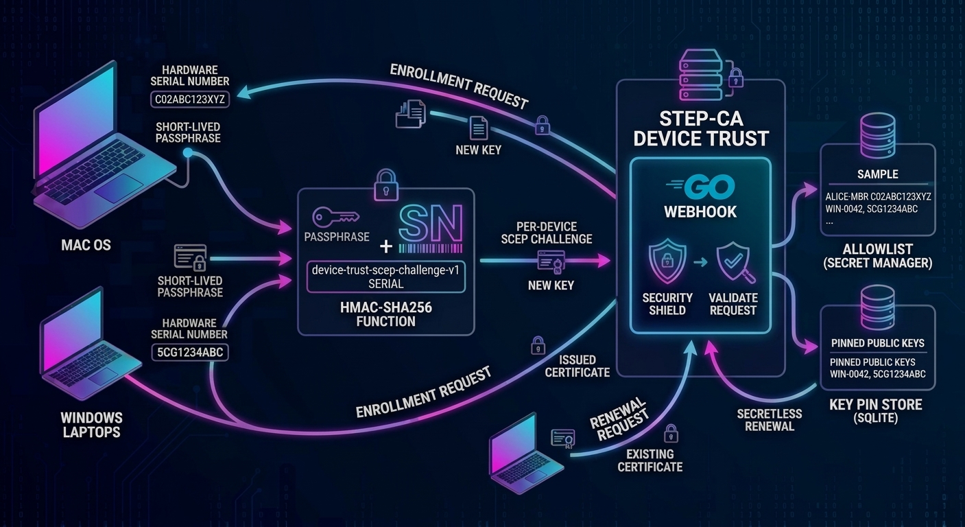
Every certificate-based device trust build I have written shares one uncomfortable detail: a single SCEP challenge password that every endpoint presents to get a certificate. It lives in a Secret Manager secret, travels through a Terraform output, and ends up in an MDM script run on every device in the fleet. Anyone who can read that script on one machine, or pull it from one compromised endpoint, can enroll any device they like, indefinitely. The fix is a per-device SCEP challenge.
This project closes that gap for the Google Cloud blueprint. It allows adding a small Go webhook that runs next to step-ca and issues a per-device SCEP challenge to every endpoint, makes enrollment phrases short-lived and single use, and lets enrolled devices renew without any shared secret at all. It builds directly on three earlier posts: the original design for device trust with step-ca and Google Cloud CAS, the Terraform blueprint that automates it, and the device trust gateway that acts as another layer of controls consuming the resulting certificates. The first two are the context for everything below, and the project repository has the code.
Where the earlier builds left a gap
The original Terraform blueprint generates one challenge password, keeps it in Secret Manager, and hands it to the enrollment scripts as a parameter. The original design post already named this as a weakness: the challenge is a shared secret, so it suggested separate provisioners for different device types and looking at client-side registration authorities or EST for stronger authentication. Both help, but neither removes the core problem of one secret shared across many devices.
Certificate lifetimes make it worse. The design post recommends short-lived certificates, roughly 7 to 45 days, renewed automatically. Every renewal then replays the same shared secret from every device, over and over. And the Delete key-protection mode in the blueprint, which discards the loose private key after import so the key stays non-exportable, forces a complete new enrollment, shared secret included, at every renewal.
What I wanted instead was four properties:
- Per device. A challenge that is only valid for one specific machine, derived from something the machine knows about itself and the server can look up.
- Short lived. The one thing the whole fleet receives should expire.
- Single use. One enrollment per device per secret, so a leaked value cannot be replayed.
- Renewal without a fleet-wide secret. Rotating certificates should not mean redistributing credentials.
This is not device attestation. Hardware attestation would prove which physical device is asking, but it needs an attestation authority and a verification service, and it is better maintained by the device manufacturer. What follows limits exposure and raises the cost of abuse. It does not prove identity, and the Limits section covers where it falls short.
The per-device idea has a name elsewhere. Several products offer a dynamic SCEP challenge: Infisical, for example, issues single-use challenges that expire after a configurable time and lets an MDM fetch them. Smallstep gives you the hook to build the same thing yourself: a SCEPCHALLENGE webhook that replaces the static challenge and decides, per request, whether to allow it. RFC 8894 points the same way, saying that a renewing client should normally omit the challenge password and that the CA should not authenticate a renewal on a self-signed certificate alone.
The per-device SCEP challenge design in four moving parts
1. The challenge is a keyed hash of the serial number
The device reads its own hardware serial number and computes the challenge from the current enrollment phrase, a short diceware-style passphrase. The server recomputes the same value and compares.
challenge = base64( HMAC-SHA256( key = phrase, message = "device-trust-scep-challenge-v1\n" + SERIAL ) )
I first sketched this as AES encryption of the phrase with the serial as the key, mostly because AES is available everywhere. HMAC is available everywhere too (OpenSSL, the .NET HMACSHA256 class, Go) and it is the better fit: it is one-way, so a leaked challenge reveals nothing about the phrase, and serial numbers are not secret, so the phrase must be the key rather than the message. Serial numbers are trimmed and upper-cased on both sides. Here is the same known answer from OpenSSL and PowerShell, which also agree with the Go server:
# OpenSSL (macOS, Linux)
printf 'device-trust-scep-challenge-v1\n%s' "C02ABC123XYZ" | openssl dgst -sha256 -hmac "Queen-Ate-Lamp-Wise-Smell" -binary | openssl base64 -A
# 6ZR262r4trPJ6vKSEOgBATU4m8NXj97z0oOmBt/wo8c=

# PowerShell (Windows)
$h = New-Object System.Security.Cryptography.HMACSHA256
$h.Key = [Text.Encoding]::UTF8.GetBytes("Queen-Ate-Lamp-Wise-Smell")
[Convert]::ToBase64String($h.ComputeHash([Text.Encoding]::UTF8.GetBytes("device-trust-scep-challenge-v1`n" + "C02ABC123XYZ")))
# 6ZR262r4trPJ6vKSEOgBATU4m8NXj97z0oOmBt/wo8c=
2. An allowlist maps hostnames to serial numbers
The CSR carries only a claim, the hostname in the common name. The webhook looks that hostname up in an allowlist of HOSTNAME,SERIAL lines and computes the expected challenge from the serial recorded there. A personal device that is not listed is refused even if its owner has the phrase, and claiming someone else’s hostname fails unless you also know their serial. In the Google Cloud blueprint the allowlist is a Secret Manager secret, so an inventory system such as Snipe-IT can publish a new version daily and the VM picks it up within five minutes.
3. Phrases are short lived and single use
Phrases are generated on the step-ca VM with sudo dtw phrase new, which draws five random words from a list you provide. The EFF wordlists work: their one-word-per-line format with a leading dice number is accepted as is. Each phrase has an expiry, can be revoked, and each host can use it once. Several phrases can be active at the same time so a rollover does not strand anyone.
4. Two provisioners, one webhook, and a key pin for renewals
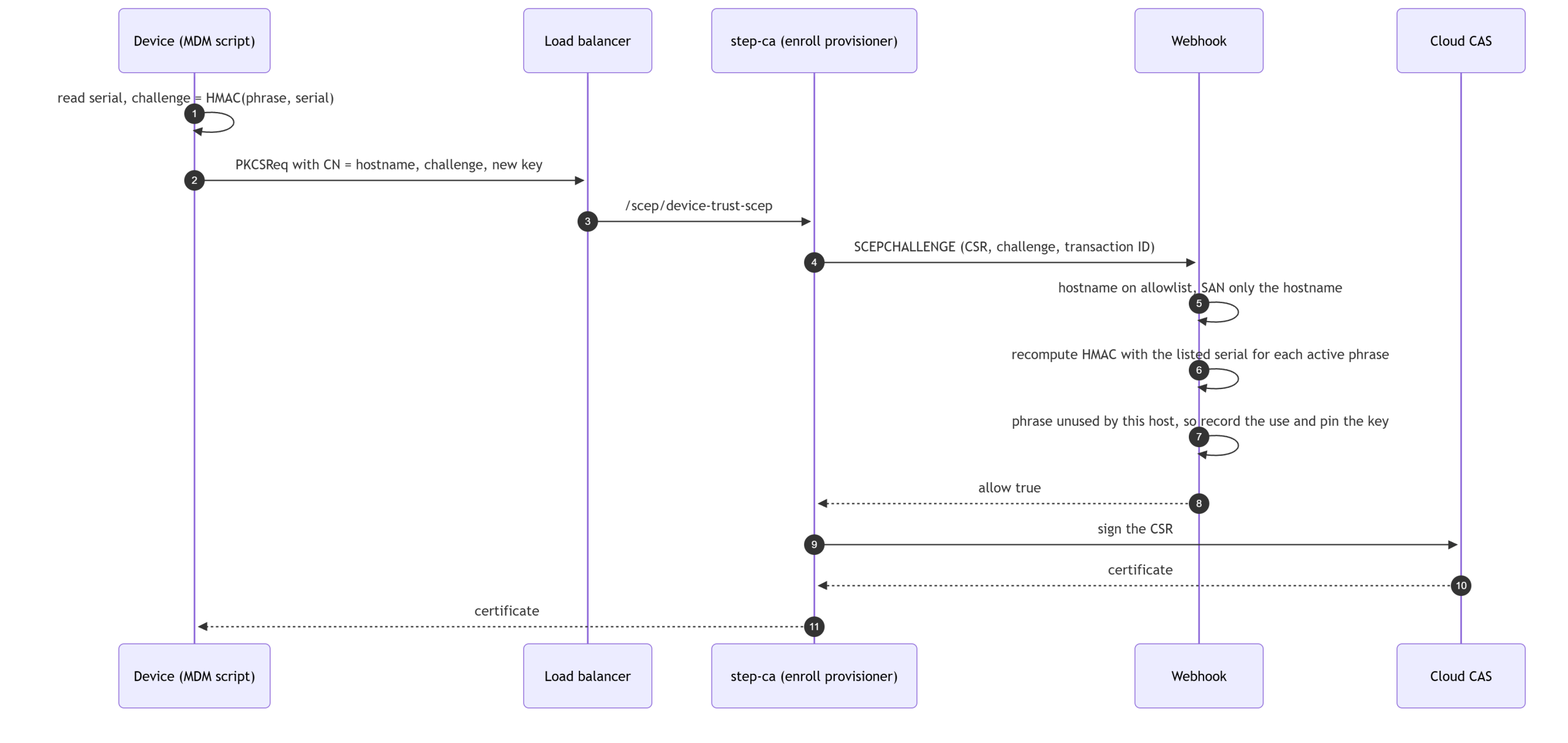
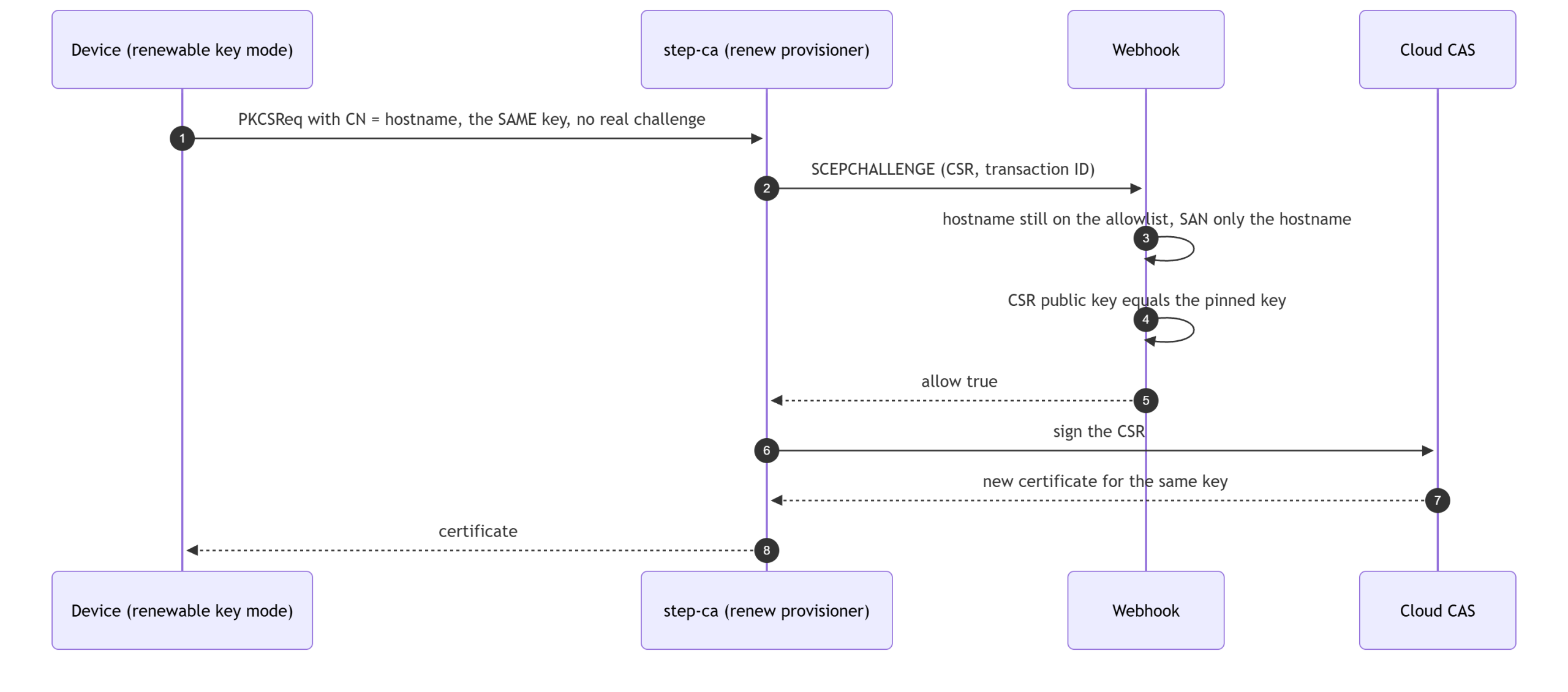
step-ca cannot tell a first enrollment from a renewal in the webhook payload, but it does send the provisioner name. So the Terraform now creates two SCEP provisioners on the same CA, both calling the same webhook, and the webhook applies different rules to each:
| Enrollment (device-trust-scep) | Renewal (device-trust-scep-renew) | |
|---|---|---|
| Used for | First certificate, replacement device, new key | Refreshing an enrolled device’s certificate |
| Proof | Challenge from the serial number and a current phrase | The CSR carries the public key the host enrolled with |
| Phrase needed | Yes, once per host per phrase | No |
| Host on allowlist | Required | Required |
| Effect | Records the CSR public key as the host’s pin | None |
The pin is what makes secretless renewal safe. A certificate issued for a pinned public key is useless to anyone without the matching private key, so the worst a stranger can get from the renewal endpoint is a fresh certificate for a device’s own key. The pin also ties the request to the claimed hostname, so one device cannot renew as another.
A gap the certificate template opens
The certificate template in this repository copies the CSR’s subject and subject alternative names straight into the issued certificate. Without a check, a host that is allowed to enroll as laptop-01 could add laptop-02 to its SANs and receive a certificate naming something else. The webhook therefore denies any request whose SAN extension holds anything other than DNS names equal to the claimed hostname or its subdomains. I tested this with real requests, covered in the results below.
What changed in the architecture
Nothing about the public surface changes: the load balancer still routes only /scep/*, step-ca still has no external IP, and Cloud CAS still holds the keys. The new pieces all live on the existing step-ca VM or beside it in Secret Manager.
![flowchart LR
subgraph Fleet["Managed endpoints (macOS, Windows, Linux)"]
MDM["MDM job runs the install script"]
end
Inv["Inventory sync job (Snipe-IT or similar)"]
Admin["Admin over IAP SSH: sudo dtw ..."]
subgraph GCP["Google Cloud project"]
LB["External HTTPS load balancer: only /scep/* is routed"]
subgraph VM["step-ca VM (no external IP)"]
SC["step-ca in cloudCAS RA mode<br/>device-trust-scep (enroll)<br/>device-trust-scep-renew (renew)"]
WH["device-trust-webhook<br/>https on 172.17.0.1:8081"]
DB[("SQLite on a persistent disk:<br/>phrases, uses, pinned keys")]
end
SM["Secret Manager:<br/>allowlist, webhook TLS cert and key"]
CAS["Cloud CAS: root CA and intermediate CA"]
GW["Device trust gateway (nginx, client certificates)"]
end
MDM -->|"SCEP over HTTPS"| LB
LB --> SC
SC -->|"SCEPCHALLENGE webhook"| WH
WH --- DB
SM -->|"re-read every 5 minutes"| WH
SC -->|"sign request"| CAS
Inv -->|"new allowlist version"| SM
Admin --> WH
MDM -.->|"issued certificate, mTLS"| GW](https://hackersvanguard.com/wp-content/uploads/2026/10/mermaid-diagram-2026-10-15-211525-scaled.png)
The persistent state, meaning phrases, usage records and pinned keys, lives in SQLite on its own independent disk so that recreating the VM does not make every device enroll again.
The flows
Enrollment
Renewal
The decision, in one picture
![flowchart TD
A["Webhook request"] --> B{"Which provisioner?"}
B -->|"not one of ours"| X["Deny"]
B -->|"enrollment"| E1{"Host listed and<br/>SAN only the hostname?"}
B -->|"renewal"| R1{"Host listed and<br/>SAN only the hostname?"}
E1 -->|"no"| X
E1 -->|"yes"| E2{"Challenge matches an active<br/>phrase for the listed serial?"}
E2 -->|"no"| X
E2 -->|"yes"| E3{"Phrase already used<br/>by this host?"}
E3 -->|"yes, other transaction"| X
E3 -->|"no, or a retry of the same transaction"| OK1["Allow and pin the CSR public key"]
R1 -->|"no"| X
R1 -->|"yes"| R2{"CSR public key equals<br/>the pinned key?"}
R2 -->|"no, or no pin"| X
R2 -->|"yes"| OK2["Allow, no phrase involved"]](https://hackersvanguard.com/wp-content/uploads/2026/10/mermaid-diagram-2026-10-15-211914-scaled.png)
Choose how the device keeps its key
Renewal by key pin only works if the device can still use the key it enrolled with. That is a decision about where the private key lives after the certificate is installed, and the Terraform blueprint post already introduced the trade-off for Windows with the -KeyProtection flag. The new design supports both ends of it, per device group, and a mixed fleet is fine because the webhook never needs to know which mode a host uses.
| Renewable key | Delete after import | |
|---|---|---|
| Where the key lives | In a root or Administrators-only directory, and in the keychain or certificate store imported non-exportable | Only in the keychain or certificate store, imported non-exportable. The loose files are deleted |
| Renewal | Same key, renewal provisioner, no phrase | No key to reuse, so every renewal is a new enrollment with that cycle’s phrase and a fresh key |
| Phrase distribution | Only for onboarding batches | To the whole fleet every cycle |
| Key rotation | The key never changes unless you re-enroll | A new key every cycle |
| Standard (non-admin) user | Windows: cannot read the key file, and the store copy is non-exportable. macOS: cannot read the key file as its non-exportable in user login keychain. | Cannot read the key; the store copy is non-exportable |
| Administrator on the device | Can read the key file, so can copy it to another machine, and keeps renewal rights until you remove the host or clear its pin | The stored key is non-exportable through normal tools, but an administrator can still use it locally and can see the phrase when it is delivered |
| Cost per renewal | One certificate issuance | One certificate issuance |
Use renewable for Windows devices whose users are not local administrators; it removes the monthly fleet-wide phrase entirely. On a Mac the user cannot read the key file unless they have sudo, so I would choose delete after import there unless that exposure is acceptable. Use delete after import where users are administrators and you accept that the phrase is exposed to those devices every cycle. Neither mode is attestation: non-exportability stops a standard user, not an administrator. A hardware-bound key would close that gap, but scepclient cannot sign with one, so it is out of scope here.
One correction to the blueprint post, which describes reusing the key as cheaper under CAS per-certificate billing. In testing, a same-key renewal still produced a new certificate with a new serial number, and Cloud CAS bills per certificate issued on the Enterprise tier either way. It could be possible to save on the per-certificate billing if you only use CAS to issue step-ca VMs their own subordinates CA, which can issue device trust leaf certificates. But that’s an entirely different set of design constraints and could easily result in dangling leaf’s without a full chain of trust. What the renewable mode saves is the shared secret and the key churn, not money.
![flowchart LR
subgraph Renewable["Renewable key"]
A1["Day 0: enroll with the phrase<br/>key file kept, locked down"] --> A2["Day 30: renew, same key, no phrase"] --> A3["Day 60: renew, same key, no phrase"]
end
subgraph Delete["Delete after import"]
B1["Day 0: enroll with phrase 1<br/>import non-exportable, delete key files"] --> B2["Day 30: enroll with phrase 2<br/>fresh key, pin replaced"] --> B3["Day 60: enroll with phrase 3<br/>fresh key, pin replaced"]
end](https://hackersvanguard.com/wp-content/uploads/2026/10/mermaid-diagram-2026-10-15-212040.png)
Try it: the install scripts for macOS and Windows
The blueprint already ships install scripts for macOS and Windows that request the certificate, import it and test it against the mTLS gateway, so the webhook support went into those instead of becoming a second set of scripts. Four optional settings turn it on, and with all of them unset the scripts behave exactly as before. The same goes for the Terraform: the whole feature is off unless you set enable_webhook.
| Setting | What it does |
|---|---|
SCEP_PHRASE (-ScepPhrase) | The current enrollment phrase. The script reads the serial number and computes the challenge itself |
SCEP_RENEW_PROVISIONER (-RenewProvisioner) | The renewal provisioner. Used instead of enrolling when the key from the last run is still on disk, so renewal needs no phrase |
KEY_PROTECTION (-KeyProtection) | Delete or RestrictPermissions. Windows defaults to Delete as before; on macOS it is opt-in |
SCEP_ATTEMPTS (-ScepAttempts) | Tries per scepclient call, default 3 |
A refused renewal falls back to enrolling with a new key when a phrase is set, which is what happens after an administrator clears a host’s pin. The challenge is never printed. The core of the macOS version is below, copied from install-macos.sh: it reads the serial number, computes the challenge, and picks enrollment or renewal. It uses settings the script reads earlier (SCEP_PHRASE, SCEP_RENEW_PROVISIONER, whether a key from the last run exists), so read it as an excerpt of the script, not a standalone file.
# This Mac's serial number, as the server's allowlist records it: trimmed and
# upper-cased. DEVICE_SERIAL overrides the hardware lookup (virtual machines
# and test rigs that have no IOPlatformSerialNumber).
device_serial() {
    if [ -n "${DEVICE_SERIAL:-}" ]; then
        printf '%s' "$DEVICE_SERIAL"
    else
        ioreg -rd1 -c IOPlatformExpertDevice | awk -F'"' '/IOPlatformSerialNumber/{print $4}'
    fi
}
normalized_serial() {
    device_serial | tr -d '\r\n' | sed 's/^[[:space:]]*//;s/[[:space:]]*$//' | tr '[:lower:]' '[:upper:]'
}
phrase_challenge() {
    local serial
    serial=$(normalized_serial)
    if [ -z "$serial" ]; then
        printf "${RED}Error: could not read this Mac's serial number to build the per-device challenge${NC}\n" >&2
        return 1
    fi
    printf 'device-trust-scep-challenge-v1\n%s' "$serial" | openssl dgst -sha256 -hmac "$SCEP_PHRASE" -binary | openssl base64 -A
}

# Renew with the key from the last run when we can (webhook mode); otherwise
# enroll. Without SCEP_PHRASE and SCEP_RENEW_PROVISIONER this is the original
# behaviour: one provisioner, the static challenge.
ACTION=enroll
ACTIVE_PROVISIONER="$SCEP_PROVISIONER"
ACTIVE_CHALLENGE="$SCEP_CHALLENGE"
CHALLENGE_NOTE="static SCEP_CHALLENGE (per-device challenges are not in use)"
if [ -n "$SCEP_RENEW_PROVISIONER" ] && [ "$HAVE_KEY" -eq 1 ]; then
    ACTION=renew
    ACTIVE_PROVISIONER="$SCEP_RENEW_PROVISIONER"
    ACTIVE_CHALLENGE="not-used-for-renewal"      # the renewal path ignores it
    CHALLENGE_NOTE="renewal with the key from the last run; no phrase or challenge is sent, the server checks the key against the one pinned at enrollment"
elif [ -n "$SCEP_PHRASE" ]; then
    ACTIVE_CHALLENGE=$(phrase_challenge)
    CHALLENGE_NOTE="per-device challenge from this Mac's serial number $(normalized_serial) (HMAC-SHA256 keyed by the phrase; the phrase and the challenge are not shown)"
fi
macOS, renewable key
Run it with sudo -E as the logged-in user. The first run enrolls with the phrase; every later run renews with no phrase. The identity goes into the login keychain with -x, which marks the key non-exportable. The key file stays in ~/.device-trust so the next run can reuse it. Expect one more prompt the first time a browser uses the certificate: Safari asks for access to the login keychain, because the import only grants the security tool silent access to the key. That is normal, and it is the user’s own password or Touch ID.
export SCEP_SERVER_URL="https://213.0.0.10"
export MTLS_GATEWAY_URL="https://213.0.0.20/"
export SCEP_PROVISIONER=device-trust-scep      # the script's default is a placeholder
export ROOT_CA_FILE_SRC=./root-ca.crt
export SCEP_RENEW_PROVISIONER=device-trust-scep-renew
export KEY_PROTECTION=RestrictPermissions

# first run: enroll (the phrase comes from your MDM for this onboarding batch)
SCEP_PHRASE="$PHRASE_FROM_MDM" sudo -E ./install-macos.sh

# every later run: renew with the same key, no phrase
sudo -E ./install-macos.sh
macOS, delete after import
This is the new part for macOS, and it is opt-in. The script imports the identity, runs the mTLS test with the loose files, and only then deletes them, so a run proves ClientAuth works before the key is gone. Every run is a new enrollment with that cycle’s phrase.
if [ "$KEY_PROTECTION" = "Delete" ]; then
    rm -f "$PRIVATE_KEY_FILE" "$CERT_FILE" "${CERT_DIR}/csr.pem" "${CERT_DIR}/self.pem"
    printf "${GREEN}Deleted the loose private key, certificate and cached CSR. The key now lives only in the keychain (non-exportable); the next run enrolls with a new key.${NC}\n"
elif [ "$KEY_PROTECTION" = "RestrictPermissions" ]; then
    chmod 700 "$CERT_DIR"
    chmod 600 "$PRIVATE_KEY_FILE"
    printf "${GREEN}Kept the key for same-key renewal, mode 600 in a mode 700 directory.${NC}\n"
    printf "${YELLOW}Note: on macOS it stays readable by ${TARGET_USER}. Use KEY_PROTECTION=Delete where that is not acceptable.${NC}\n"
fi
# same SCEP_SERVER_URL, SCEP_PROVISIONER and ROOT_CA_FILE_SRC exports as above.
# Every cycle, including the first: this cycle's phrase, a fresh key, import, then delete
export KEY_PROTECTION=Delete
SCEP_PHRASE="$PHRASE_FROM_MDM" sudo -E ./install-macos.shWindows, both modes
Run install-windows.ps1 from an elevated prompt or as SYSTEM from your MDM; install-windows.bat takes the same settings as environment variables. Renewable mode locks the key to SYSTEM and Administrators with icacls, so a standard user cannot read it. Delete mode imports with NoExport and then removes the files. If PowerShell refuses with “running scripts is disabled on this system”, allow it for that one window only with Set-ExecutionPolicy -Scope Process -ExecutionPolicy Bypass -Force; it reverts when the window closes.
# This PC's serial number, as the server's allowlist records it: trimmed and
# upper-cased. DEVICE_SERIAL overrides the hardware lookup (virtual machines
# and test rigs that report a placeholder serial).
function Get-DeviceSerial {
    if ($env:DEVICE_SERIAL) { return $env:DEVICE_SERIAL }
    (Get-CimInstance Win32_BIOS).SerialNumber
}
function Get-NormalizedSerial { (Get-DeviceSerial).Trim().ToUpperInvariant() }
function Get-PhraseChallenge {
    $serial = Get-NormalizedSerial
    if (-not $serial) { throw "Could not read this PC's serial number to build the per-device challenge" }
    $h = New-Object System.Security.Cryptography.HMACSHA256
    try {
        $h.Key = [Text.Encoding]::UTF8.GetBytes($ScepPhrase)
        $msg = [Text.Encoding]::UTF8.GetBytes("device-trust-scep-challenge-v1`n$serial")
        [Convert]::ToBase64String($h.ComputeHash($msg))
    } finally { $h.Dispose() }
}

# One scepclient request, retried up to -ScepAttempts times (see the parameter
# comment). Returns $true on success. Out-Host keeps scepclient's output out of
# the return value.
# usage: Invoke-ScepRequest <key-file> <cert-file> <provisioner> <challenge>
function Invoke-ScepRequest([string]$KeyFile, [string]$CertOut, [string]$ForProvisioner, [string]$ForChallenge) {
    for ($attempt = 1; $attempt -le $ScepAttempts; $attempt++) {
        $KeyDir = Split-Path -Parent $KeyFile
        Remove-Item -Path (Join-Path $KeyDir "csr.pem") -Force -ErrorAction SilentlyContinue
        if (-not (Test-Path -Path $KeyFile)) { Remove-Item -Path (Join-Path $KeyDir "self.pem") -Force -ErrorAction SilentlyContinue }
        & $ScepTool -private-key $KeyFile -certificate $CertOut -server-url "$ScepServerUrl/scep/$ForProvisioner" -challenge $ForChallenge -dnsname $DnsName -cn $CommonName -country $Country -organization $Organization -ou $Ou | Out-Host
        if ($LASTEXITCODE -eq 0) { return $true }
        if ($attempt -lt $ScepAttempts) {
            Write-Warning "scepclient attempt $attempt of $ScepAttempts failed - retrying in 2 seconds"
            Start-Sleep -Seconds 2
        }
    }
    return $false
}

# Renew with the key from the last run when we can (webhook mode); otherwise
# enroll. Without -ScepPhrase and -RenewProvisioner this is the original
# behaviour: one provisioner, the static challenge.
$Action = "enroll"
$ActiveProvisioner = $Provisioner
$ActiveChallenge = $Challenge
$ChallengeNote = "static SCEP_CHALLENGE (per-device challenges are not in use)"
if ($RenewProvisioner -and $HaveKey) {
    $Action = "renew"
    $ActiveProvisioner = $RenewProvisioner
    $ActiveChallenge = "not-used-for-renewal"      # the renewal path ignores it
    $ChallengeNote = "renewal with the key from the last run; no phrase or challenge is sent, the server checks the key against the one pinned at enrollment"
} elseif ($ScepPhrase) {
    $ActiveChallenge = Get-PhraseChallenge
    $ChallengeNote = "per-device challenge from this PC's serial number $(Get-NormalizedSerial) (HMAC-SHA256 keyed by the phrase; the phrase and the challenge are not shown)"
}
$env:SCEP_SERVER_URL = "https://213.0.0.10"
$env:MTLS_GATEWAY_URL = "https://213.0.0.20/"
$env:SCEP_PROVISIONER = "device-trust-scep"
$env:ROOT_CA_FILE = ".\root-ca.crt"      # install-windows.bat reads ROOT_CA_FILE_SRC instead
$env:SCEP_RENEW_PROVISIONER = "device-trust-scep-renew"

# Renewable key: the first run enrolls, later runs renew with no phrase
$env:SCEP_PHRASE = "<this onboarding batch's phrase>"
.\install-windows.ps1 -KeyProtection RestrictPermissions
.\install-windows.ps1 -KeyProtection RestrictPermissions

# Delete after import, on a device that does not keep a key: every cycle enrolls with that cycle's phrase,
# imports NoExport, then deletes the key. (With a key still on disk and the renewal provisioner set,
# the script renews with that key instead.)
$env:SCEP_PHRASE = "<this cycle's phrase>"
.\install-windows.ps1 -KeyProtection Delete
The server keeps the other half of the record: sudo dtw uses list shows which host used which phrase, and sudo dtw pins list shows the fingerprint of the key it enrolled with.
Deploying and operating it
The webhook is optional and off by default. Build the Linux binary, point Terraform at it, and list your devices (the webhook README has every command and setting):
cd webhook && CGO_ENABLED=0 GOOS=linux GOARCH=amd64 go build -o device-trust-webhook . && cd ..

# terraform.tfvars
enable_webhook      = true
webhook_binary_path = "webhook/device-trust-webhook"
scep_cert_lifetime  = "1080h"     # 45 days; step-ca's default is 24 hours

webhook_devices = <<-EOT
  # hostname,serial,note
  ALICE-MBP,C02ABC123XYZ,Alice's MacBook
  WIN-0042,5CG1234ABC
EOT
Apply it and the existing device-trust-scep provisioner becomes the enrollment provisioner, device-trust-scep-renew appears beside it, and the static challenge stops being used. Anything still sending the old shared challenge will be refused, so roll the new scripts out first or at the same time. With enable_webhook left at false, nothing changes.
Day to day, everything is a dtw command on the VM, reached over IAP, plus a Secret Manager secret for the allowlist:
gcloud compute ssh step-ca --zone us-central1-a --tunnel-through-iap

sudo dtw phrase new -wordlist /path/to/eff_large_wordlist.txt -expires-in 72h   # prints only the phrase
sudo dtw phrase list          # status, expiry, how many hosts used each
sudo dtw uses list            # which host enrolled with which phrase, and when
sudo dtw pins list            # the key fingerprint each host enrolled with
sudo dtw pins clear ALICE-MBP # that host must enroll again before it can renew
sudo dtw uses reset ALICE-MBP # let it retry a phrase it already used (issuance failed)

# decommission a device: publish an allowlist version without it
gcloud secrets versions add step-ca-dtw-devices --data-file=devices.csv
Removing a device from the allowlist stops its renewals within minutes, and its current certificate runs out at expiry, so revoke it too if you need it gone immediately. Replacing a device or giving it a new key is just another enrollment under a fresh phrase, which replaces the pin. The pins are the only record of which key each host enrolled with, so back up the disk; if the database is lost, every host enrolls again.
What I tested
I built the whole per-device SCEP challenge setup four times. The first environments found the bugs; each time I destroyed everything, fixed the Terraform, and rebuilt from scratch on new CA pool names. The last two rebuilds tested the install scripts themselves, and the final one ran from the exact commit in the pull request, first as a default build with the webhook off and then switching the webhook on over the running deployment: the Windows scripts on a real Windows Server 2022 VM, and the macOS script in a Linux container that stood in for a Mac, both using scepclient 2.3.0 from micromdm/scep. Then I ran the scripts on real hardware against the same deployment: install-windows.ps1 on a Windows 11 PC, and install-macos.sh on an Apple Silicon Mac mini, each enrolling with a phrase, renewing with no phrase, and doing a one-time delete-mode enrollment.
Limits, stated plainly
- This is not attestation. The hostname is a claim and the serial number is the only link to hardware, and serial numbers are on the sticker and in your inventory.
- Someone holding the current enrollment phrase who also knows a listed device’s hostname and serial, and who reaches the enrollment endpoint first, can enroll as that device and pin their own key. Single use means whoever enrolls first in a phrase’s lifetime wins.
- Devices that already hold certificates from before the webhook have no pin and must re-enroll
- Single use records the webhook’s decision, not that a certificate was issued. If issuance fails after the webhook said yes,
dtw uses resetunlocks the host. - In renewable mode an administrator on the device can copy the key. That is the price of renewal without a phrase, and it is why I would choose delete after import for devices whose users are administrators.
- VMs and white-box PCs often report placeholder serials such as “To Be Filled By O.E.M.”. Check what your fleet actually returns before you build the inventory; duplicate serials are rejected when the allowlist loads.
Compared with the shared challenge it replaces, a per-device SCEP challenge shrinks the blast radius from the whole fleet to one device; a leaked phrase expires, and a stranger with a phrase gets nothing without also knowing a device’s hostname and serial.
Where to go next
- The Device-Trust-Cloud repository has the Terraform, the webhook, and the install scripts, with a README for the whole project and a README for the webhook.
- Smallstep’s webhooks documentation, SCEP provisioner reference and the example webhook server cover the mechanism this builds on.
- RFC 8894 is the SCEP specification; section 2.4 covers renewal and the challenge password.
- To see what the issued certificates are for, read the device trust gateway post and Identity Provider Empowered Device Trust, and for the motivation why certificate-based device trust matters.
If you build on this, I would like to hear what breaks. The sharpest open question is how to prove a renewal with the old certificate instead of a key pin, which needs step-ca to verify the SCEP message signer. At the version I tested, step-ca leaves that as a TODO in the renewal path.