Halloween is my favorite time of year, and I love creating interactive experiences for trick-or-treaters. Last year, Alex Volkov’s project on Weights & Biases – building an AI-powered skeleton using a Raspberry Pi – sparked an idea. This year, I wanted to take that concept further, aiming for a smaller footprint and increased processing power by leveraging the Radxa Zero 3W single board computer. This blog post details my journey of transforming a standard Home Depot 3ft Halloween Classics Animated LED Dancing Skeleton into a locally AI-driven greeter. We’ll cover everything from dismantling the original animatronic, wiring up the Radxa Zero 3W, and setting the stage for integrating local vision models to recognize costumes.
The Inspiration & Goals
Volkov’s project was brilliant: using online AI services like Google AI Studio, ElevenLabs (for voice), Cartesia, and ChatGPT to create a responsive skeleton that could greet trick-or-treaters. However, relying on cloud services introduces latency, requires a stable internet connection, and could raise privacy concerns – not ideal for the often chaotic Halloween night. My goal was to replicate the interactive experience but move all processing local, using a more compact and powerful board than the Raspberry Pi 4. The Radxa Zero 3W seemed like the perfect fit. It packs significant punch in a tiny form factor, offering Wi-Fi connectivity, Bluetooth, and ample GPIO pins for controlling the animatronic components.
Disassembly & Component Identification: Getting to Know Skelly
The first step was understanding how the original skeleton worked. This involved carefully dismantling the 3ft dancing skeleton. Start by removing the back of the skull and chest plate; this provides access to the control board, battery pack, motors, and speaker. Be gentle – these animatronics aren’t built for extensive tinkering!
Inside the skull, you’ll find a DC motor controlling the mouth movement (yellow positive, white ground wires) and LEDs illuminating the eyes (red positive, black ground wires).
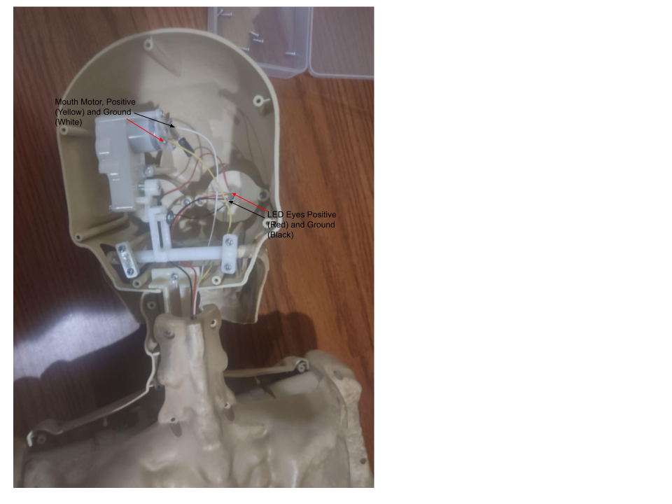
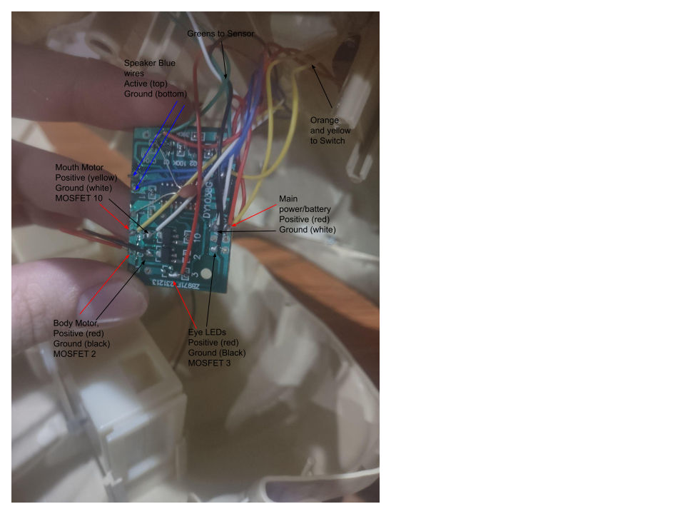
Under the chest plate you will see a hardware speaker with two blue wires and another DC motor powering the body/arm movements (positive red, ground black). All these wires converge on a small control board.
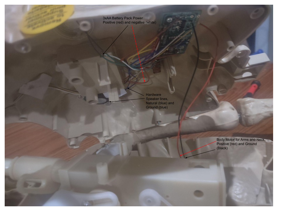
It’s crucial to document everything as you go. I took numerous photos and created a wiring diagram to ensure I could reassemble everything correctly (or at least understand where things went if something went wrong!).
The original manufacturer uses transistors and capacitors to compensate for the fluctuating battery voltage – typically between 1.4V and 1.66V with three AA batteries in parallel, reaching around 5V. This is a good reminder that relying solely on the battery pack’s power output isn’t ideal; we’ll address this later.
Wiring Up the Radxa Zero 3W: The Heart of the Operation
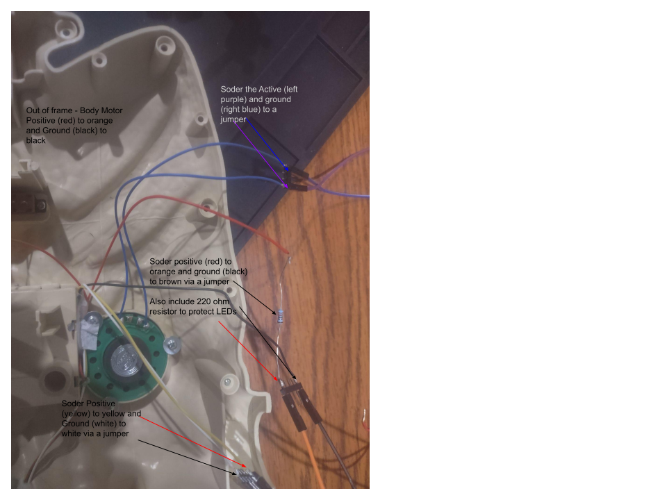
The plan was to intercept the signals going to each component – mouth motor, eye LEDs, body motor, and speaker – and control them via the Radxa Zero 3W’s GPIO pins. This required carefully unsoldering these wires from the original control board.
Once unsolder, I connected each wire to a set of jumper pins, allowing me to easily breadboard and test connections before committing to permanent soldering. This also provides flexibility for future modifications.
Note: I included a 220 Ohm inline to help prevent the eye LEDs from burning out. Its not required, but its recommended to avoid burning out the LEDs during tinkering.
Here’s the GPIO pinout I utilized on the Radxa Zero 3W (gpiochip3):
- PIN_7 (gpiochip3 20) – Mouth motor open/close
- PIN_11 (gpiochip3 1) – Eye LEDs illumination
- PIN_15 (gpiochip3 8) – Body motor for dancing movement
The Radxa Zero 3W’s official documentation outlines the 40-pin GPIO interface. Since we’re using pins 12, 40 and 35 for our mono amp (more on that later), this leaves a good selection of readily available pins on gpiochip3 to control relays.
- Pin 7: GPIO3_C4 (also PWM14_M0)
- Pin 11: GPIO3_A1
- Pin 15: GPIO3_B0
- Pin 16: GPIO3_B1 (also PWM8_M0)
Note: PWM (Pulse-Width Modulation) can be used on Pin 7 and Pin 16 by enabling the correct device tree overlay using
rsetupand/or u-boot. This allows for finer control over LEDs (dimming) and DC motor speeds, but wasn’t necessary for this initial implementation.
Powering Skelly: The Radxa Zero 3W to the Rescue
Initially, I considered powering the components directly from the battery pack. However, as mentioned earlier, the inconsistent voltage proved problematic. The solution? Leverage the Radxa Zero 3W’s 5V GPIO power rails! This provides a stable and reliable power source for all components.
To manage the current requirements of the motors and LEDs, I incorporated relays inline with each component’s wiring. Relays act as electrically controlled switches, allowing the Radxa Zero 3W to control the flow of power from its 5V output to the skeleton’s components.
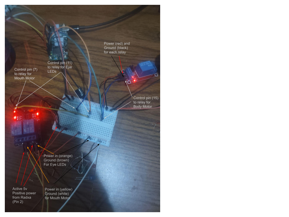
Relay Implementation: The Switching Mechanism
Each relay requires a control pin on the GPIO, which when activated, allows power to flow through it. The wiring is as follows:
- Connect the Radxa Zero 3W’s 5V output to both sides of each relay.
- Ground each relay and component to the Radxa Zero 3W’s ground pins.
- Connect the control pin on the GPIO to the relay’s control input.
- The output power of each relay connects to the corresponding component’s jumper (mouth motor, body motor, eye LEDs).
When the GPIO pin is set HIGH (active state), the relay closes, allowing power to flow from the Radxa Zero 3W to the component. When the pin is LOW, the relay opens, cutting off the power supply. This effectively gives us programmatic control over each animatronic function.
Breadboarding & Testing: Bringing it All Together
I started by breadboarding everything – connecting the Radxa Zero 3W, relays, jumpers, and a temporary power source to verify functionality. This is where patience is key! Double-check all connections before applying power. A multimeter is your best friend during this phase. Once I confirmed that each component responded correctly to the GPIO signals, I removed the breadboard and connected everything directly to the jumper wires for a more permanent connection.
Mounting & Final Assembly: Skelly Gets an Upgrade
With the wiring complete, it was time to mount the Radxa Zero 3W inside the skeleton’s chest cavity. I repurposed the original control board’s mounting point and used some 2.5mm standoffs to secure the Radxa Zero 3W in place. This ensured a snug fit without interfering with any existing components.
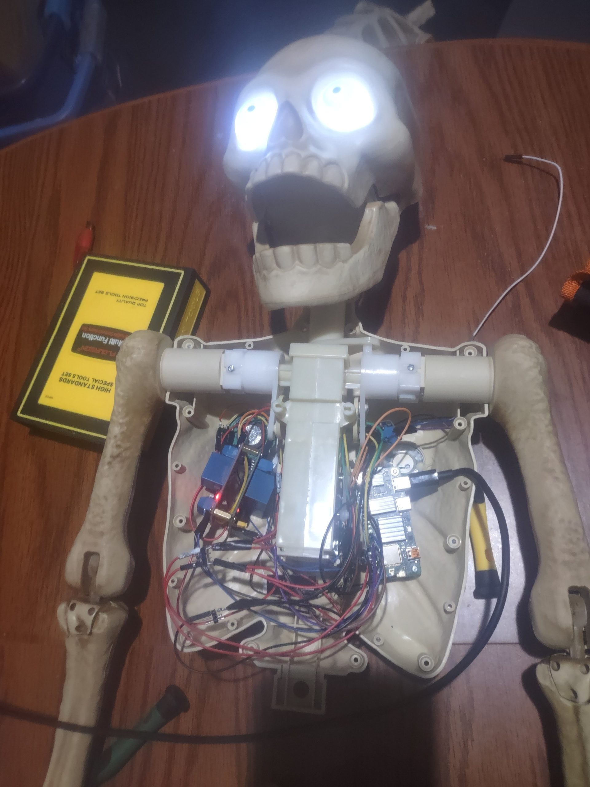
I then stuffed all the “guts” back into the body, wrote a simple web control page, using Flask, to test the functionality remotely, and ran through final testing. Success! Skelly was now responding to commands from my computer, ready for the next phase: AI integration.
The Next Phase: Local Vision Models & Costume Recognition
With Skelly reasonably buttoned up and his basic movements working, I’m moving on to the most exciting part of the project – leveraging a connected camera and locally hosted/trained vision models to determine trick-or-treaters’ costumes. This will involve using services like LMStuido on an AMD AI workstation to leverage models like Gemma 3 for vision to text. I plan to document this process in a future blog post, so stay tuned! But up next a deep dive on how to leverage device tree overlays and I2S via GPIO, to power an existing hardware speaker with a MAX98357A mono amp.
Resources & Further Exploration
- Alex Volkov’s Project: https://wandb.ai/wandb_fc/halloweave/reports/Hacking-a-skeleton-to-detect-kids-costumes-and-greet-them-with-a-custom-spooky-message–VmlldzoxMDAzOTkyMw
- Radxa Zero 3W Documentation: https://radxa.com/radxa-zero-3w
- Simple Flask GPIO Control Web App: https://gist.github.com/sleventyeleven/76a5f041eb80eb16b3782b19dfeebb22
- Offline AI with AMD Ryzen and LMStuido: https://www.amd.com/en/ecosystem/isv/consumer-partners/lm-studio.html
This project has been a fantastic learning experience, combining hardware tinkering with software development and AI integration. The Radxa Zero 3W proved to be an excellent platform for this application, offering the power and flexibility needed to bring Skelly to life. I hope this blog post inspires you to create your own interactive Halloween experiences!